
How Driver Cooling Works: Heat Transfer and Troubleshooting
MOTORSPORT KNOWLEDGE · NZ & AU
Three paths. Three different jobs.
Move heat away from the body. Supply filtered air to the helmet. Make drinking accessible. A good cockpit installation plans all three without confusing their hoses, connectors or functions.
Why heat management is a safety issue · Pre- and post-race cooling · See the system diagrams · Understand the different systems · Measured hydration research and temperature graph · Cooling terminology · Chillout manuals and videos
Driver cooling is a safety issue, not just a comfort extra
Severe overheating can leave a driver unable to continue safely. Cooling, hydration, preparation and a planned response to equipment failure belong together. A functioning cooling system is not a guarantee against heat illness, and a driver becoming unwell needs timely intervention rather than encouragement to finish the stint.
Aaron Harris: firsthand experience at the Highlands 101
Rex Harris recounts that Aaron slowed significantly before losing consciousness as he entered the pits after a stint at the Highlands 101. The team intervened, caught the car and helped revive him. This is the team's firsthand account of an overheating incident, not a measured equipment trial or a claim about lap-time gains.
That experience shapes Harris Race Radios™'s practical emphasis on cooling-system reliability, accessible hydration, driver communication and a crew response when something goes wrong. Treat the driver's condition as the priority, not the remaining laps.
Supercars medical guidance and a documented cooling-suit failure
In its 2026 heat-management advisory overview, Supercars reports that Permanent Medical Delegate Dr Carl Le identified cooling-suit malfunctions, hot ambient and cockpit conditions, long races, shorter pit stops and in-car hydration-system failures as contributors to driver heat stress.
The advisory recommends preparation and heat acclimatisation, pre-race cooling, proactive hydration, driver-mass monitoring and post-race cooling. It recognises that drivers respond differently and that responsibility is shared by drivers, teams and medical personnel. These are Supercars best-practice recommendations, not a claim that one equipment package satisfies every NZ or Australian category's rules. Speedcafe's report on the advisory provides additional context.
7NEWS reported on 23 February 2026 that David Reynolds suffered a cooling-suit failure on the first lap of the Sydney finale and required medical-centre treatment after the race. Reynolds described it as the worst he had felt in a race car. This report concerns Sydney, not Bathurst; it documents severe illness and treatment, without establishing that he lost consciousness.
Before running, test cooling and drinking systems with the driver fully equipped, check the model-specific maintenance requirements, and agree how the driver will report a failure or feeling unwell. Follow event procedures and obtain prompt medical assistance if the driver becomes unwell. Do not use these incidents as a reason to improvise treatment or continue racing with a deteriorating driver.
Before and after the stint: Arctic Heat cooling vests
Heat management extends beyond the time spent in the car. Harris Race Radios™ is an Arctic Heat dealer and offers the Arctic Heat Cooling Vest as a pre- and post-race cooling option. It complements in-car liquid cooling, helmet airflow and hydration rather than replacing them.
For the available vest range and sizing information, see our Arctic cooling vests collection.
The vest uses water-activated polymer material that is chilled before use. It is a separate approach from the ice-water circulation of a F.A.S.T. garment system or the refrigeration used by a Chillout liquid cooler. Follow the vest's instructions for activation, chilling, fit, handling and reuse; do not assume that instructions for another cooling garment apply.
For circuit, endurance, speedway and off-road teams, include vest preparation and availability in the before-and-after-stint routine: have the correctly prepared vest ready before the driver needs it, alongside access to shade or a cooler area and drinking fluids. This fits the pre- and post-race cooling approach described in the Supercars medical guidance above; that guidance is not an endorsement or measured test of this particular vest.
A cooling vest is not treatment for a driver who has collapsed or become unwell. Obtain prompt medical assistance and follow the event medical team's directions. The hydration graph below measures drinking-water conditions, not the performance of the Arctic Heat vest.
Circuit, endurance, speedway and off-road: combine the methods
Circuit and endurance racers can use liquid garment cooling, helmet airflow and hydration together. Ice-based F.A.S.T. and refrigerated Chillout liquid cooling are used mainly in circuit racing, with applications in some speedway, off-road and other racing too. These are not exclusive categories: choose the combination for the cockpit, conditions, stint length and driver.
Hydration is an important part of endurance, circuit and off-road installations, not an optional substitute for cooling. For speedway and off-road, filtered helmet air also has a major dust-control role. A long circuit stint may call for all three systems; a dusty off-road cockpit may need the same combination for different reasons.
For equipment selection rather than operating principles, use our Driver Cooling & Comfort collection.
Follow the heat, air and drinking-water paths
These are conceptual flow diagrams, not measured performance graphs or instructions for joining different brands. Arrows show the direction of flow; they do not represent temperature, flow rate or cooling capacity.
Blue path: liquid garment cooling
Cooling unit → supply hose → garment tubing → return hose → cooling unit
Heat path: driver → circulating liquid → cooling unit's heat sink.
A reservoir-based system has a finite supply of stored cooling. A refrigerated unit must reject heat through its specified installation. Neither works properly if fluid circulation is restricted. Drinking water does not belong in this garment circuit unless the exact manufacturer instructions specify it as the cooling fluid.
Green path: helmet airflow and dust control
Suitable intake location → filter and pumper → air hose → compatible helmet air inlet
For speedway and off-road, dust control matters alongside cooling and comfort. Filtered airflow helps maintain positive pressure in a suitably configured helmet, reducing dust entering around openings. Check the complete helmet, hose and pumper installation; it is not a promise of a dust-free helmet in every condition.
A pumper moves air; it does not refrigerate it. Keep the intake away from exhaust fumes and hot discharge air. A particulate filter is not protection from exhaust gases.
Amber path: drinking access throughout the stint
Drink reservoir or bottle → system-specific delivery tube → helmet connection or bite valve → driver
Plan hydration for endurance, circuit and off-road racing alongside cooling and helmet air. Delivery may be by a powered drink system or by drawing through a bite valve, depending on the equipment. Route this separately from garment coolant. Check reach, cleaning, access and the driver's disconnect procedure.
How the different systems fit into a cockpit
F.A.S.T.: ice-based liquid cooling and the circulation loop

An ice-based F.A.S.T. system circulates cooled water through a compatible garment. Ice provides the stored cooling; the pump moves the water through the garment and back. Plan ice preparation and replenishment for the stint, and follow the exact system's filling instructions. The pump is not itself a refrigerator.
Check the exact reservoir, pump, garment and coupling arrangement, then plan secure mounting and hose routing. Harris Race Radios™ is an Australasian distributor for F.A.S.T. products.
Browse the F.A.S.T. cooling and air systems range, with separate collections for F.A.S.T. cooling systems and F.A.S.T. cooling parts when identifying a complete system or replacement component.
For a model example and its supplied contents, see the F.A.S.T. 18L cooling system. For current manufacturer information, see F.A.S.T. Cooling. Do not apply another F.A.S.T. model's specifications to your installation.
Chillout: refrigerated liquid cooling needs a heat-rejection path
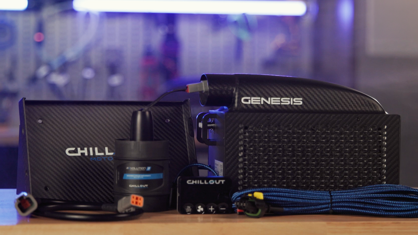
For refrigerated liquid cooling, heat carried back from the shirt must leave the cooling unit through the specified heat-rejection arrangement. Intake position, discharge routing and clearances matter as much as the cold-fluid connection. Check the model-specific manuals below. Passive PCM underwear is a separate technology, not a liquid circuit and not a refrigerated shirt.
Rugged Radios and PCI: helmet cooling, comfort and dust control

Units such as the Rugged single pumper and PCI RaceAir Pro supply helmet airflow. In dusty speedway and off-road conditions, filtered air and positive helmet pressure help reduce dust ingress as well as supporting driver comfort. Circuit and endurance racers also use helmet airflow alongside liquid cooling and drinking systems.
For range selection and installation components, see Rugged off-road air systems, forced-air helmet ducts and Maglock helmet-air systems and couplings. Select each hose, duct and coupling for the exact helmet and pumper; these collection links do not imply universal fitment.
Check filters and pre-filters according to the manufacturer's service instructions, particularly after dusty running. Inspect hose joints, restrictions and helmet-inlet fit. A blocked filter or restricted duct can reduce delivered airflow. Position the intake to avoid exhaust fumes, hot discharge air and direct dust sources where practicable.
These pumpers do not turn ambient air into refrigerated air. Check the intended number of helmets, filter condition, duct restrictions and the inlet on the exact helmet. Do not assume any hose fits any helmet or that a blower's free-air figure is the flow delivered through a complete installed hose system.
Harris Race Radios™ is an Australasian distributor for Rugged Radios and PCI. For Rugged's manufacturer range and accessory information, see Rugged Radios air pumper systems and accessories. Use the exact unit's instructions when selecting hoses, filters, controls and mounts; a manufacturer's range page does not establish compatibility with every helmet or fitting.
Helmet fit and communications still come first. Match the air inlet, drinking connection and radio installation to the correct helmet rather than choosing an unsuitable helmet just to accept a fitting. See our helmet-air ducts and accessories guidance for the air-system side of the installation.
Stilo, Rampage and Fluidlogic: hydration for endurance, circuit and off-road

Plan accessible drinking for the whole stint and a practical refill or bottle-change routine in the pits. Cooling equipment does not replace hydration. Test the drink delivery while the driver is seated, restrained and wearing the actual helmet, not just with the equipment laid out on a bench.
For practical installation, read Motorsport Driver Hydration: Setup, Use & Troubleshooting, covering delivery methods, helmet connections, tube routing, driver changes, cleaning and fault-finding.
Compare the available equipment in our driver hydration systems collection. For Stilo-specific drinking and air components, use Stilo Hydration & Top Air and confirm the fitment of the exact parts.
The Stilo hydration bag, tube and female coupling, Rampage Gen 3 drink system and Fluidlogic WAVE bottle system illustrate different ways to carry and deliver a drink. They are not interchangeable kits. The WAVE bottle uses a draw tube and bite valve; do not assume it is an automatic or powered hydration system.
Confirm reservoir mounting, tube length, helmet-side components, valve operation and the release arrangement for the exact equipment. A Stilo bag's female coupling does not establish that every helmet-side part is included. Test drinking and disconnect access with the driver wearing the actual helmet and harness, then clean and dry drinking components according to their instructions.
Measured hydration benefit: a smaller rise in core temperature
A 2025 randomized crossover trial by Bird and colleagues compared cold drinking water, approximately 5°C, with water exposed to the hot environment during simulated motor racing. Eight male volunteers undertook trials scheduled for 120 minutes in a chamber set to 40°C and 50% relative humidity, wearing motorsport protective clothing. This was a hydration study, not a test of a liquid-cooled shirt, helmet pumper or any brand sold here.

At 75 minutes: a 0.45°C smaller mean rise
Table 2 reports core-temperature increases from the start of the simulation of 1.26 ± 0.29°C with ambient water and 0.81 ± 0.30°C with cold water. The mean rise was 0.45°C smaller in the cold-water condition. This was a smaller temperature increase, not a fall below the starting temperature.
These values use the simulation start at 0 minutes as the baseline; the graph above uses −30 minutes, so its plotted heights differ from these start-to-75-minute values. Participants drank more in the cold-water condition, so the comparison does not isolate water temperature at an identical consumed volume.
All eight participants completed the cold-water trial; only two reached the full 120 minutes in the ambient-water trial. Cold water was associated with less discomfort. The practical finding is that accessible, cool drinking water can support heat management during a long hot stint. This small simulation study does not establish a temperature reduction for a particular commercial system or a lap-time benefit. Its drinking schedule is a research protocol, not an individual hydration prescription.
Assess the complete installation through a representative stint
The practical aim is to manage heat and discomfort so the driver can sustain their work through the stint. To quantify the effect in a particular car, compare representative sessions with the same driver, installation and operating conditions, recording ambient and cockpit conditions, system operation and stint duration. Review lap-time consistency alongside tyre, traffic, fuel and track changes rather than attributing every faster lap to cooling. Any physiological monitoring should use suitable equipment and qualified interpretation.
For manufacturer context on hot-cockpit racing, see Chillout's overview of NASCAR cockpit heat and cooling. It is background reading, not a measured before-and-after performance dataset.
Driver cooling is the movement of heat away from the driver. A liquid-cooled shirt, a helmet air supply and a passive temperature-regulating base layer work differently. Understanding that difference helps you diagnose a hot cockpit without treating every cooling product as interchangeable.
This knowledge guide explains principles and installation checks for New Zealand and Australian motorsport. It is not a product catalogue or a model-ranking page.
Already installing a system? Jump to Chillout manufacturer manuals and installation videos.
How does a liquid-cooled racing shirt remove heat?
A pump circulates coolant through tubing in a compatible garment. Heat passes from the driver into the circulating liquid. The cooling unit must then remove that heat from the liquid, and the installation must provide the heat-rejection path required by that unit.
The shirt, pump, cooling unit and airflow arrangement form a system. A cold reservoir alone does not establish that fluid is flowing properly through the garment. Equally, a running pump does not establish that the unit is rejecting enough heat.
What is the difference between cooling the driver and supplying helmet air?
Liquid cooling carries heat through a coolant circuit. A helmet-air system delivers air through a compatible duct and hose. A blower moves air; it does not, by itself, refrigerate it. If refrigerated helmet air is required, the system needs equipment designed for that purpose.
A cooler's condenser air circuit is also different from the air supplied to the driver's helmet. Do not connect these circuits on the assumption that every air outlet delivers cooled breathing air.
Do passive cooling base layers need a pump?
No. Phase-change-material base layers work without a circulating-liquid system. Their materials absorb heat during a phase change and release stored heat as they cool and reset. Their heat-storage capacity is finite. They are not a substitute for continuous active cooling where the installation requires it.
Temperature regulation and flame resistance are separate properties. The rating of one garment does not establish the rating of another. Use the supplied garment label and current category requirements when selecting racewear.
Why can a cooling system work in the paddock but struggle on track?
Check what changes between the two conditions: cockpit temperature, the source of cooling air, restrictions around the unit, electrical supply under load, hose routing with the driver restrained, and the duration of operation. A short static test does not reproduce a long stint.
Hot discharge air drawn back into the intake can undermine heat rejection. Tight bends, flattened ducts, blocked filters and restricted clearances can also change the installed performance. Follow the exact model's installation instructions rather than applying another cooler's duct size, fuse rating or coolant specification.
What should you check when a liquid-cooled shirt feels warm?
- Identify the exact cooler, garment, hose and connector versions before changing parts.
- Check coolant condition, level and the required blend against the manufacturer instructions. Do not mix fluids or change concentration by guesswork.
- With the equipment safely stopped as required by its instructions, inspect for kinked hoses, damaged tubing, leaks or connectors that have not engaged correctly.
- Check the unit's intake, discharge route and ventilation clearances. Keep hot exhaust air away from its intake.
- Have electrical supply, connections and circuit protection checked against the model's requirements. Do not bypass protective devices.
- Test the complete installation with the driver seated, restrained and connected before relying on it in competition.
Stop using damaged or leaking equipment and follow its service instructions. Persistent faults need diagnosis, not a larger fuse or an improvised coolant mixture.
How should cooling connections be routed for driver changes?
Check hose reach and routing in the actual driving position. Keep hoses and cables clear of pedals, steering controls, harness adjustment and the exit path. Where a release device is specified, its operation and installation must match the complete system. A connector that separates easily is not automatically an appropriate emergency release.
Practise the disconnect sequence with the car stationary and the team present. Check again after changing the seat position, helmet, harness or garment. Cooling and hydration connections need to be distinguished so the driver and crew can identify them during a change.
Does cooling replace hydration or heat-management planning?
No. Driver cooling, drinking access and cockpit airflow address different parts of the installation. Equipment cannot guarantee prevention of heat illness. If a driver becomes unwell, stop the session and seek appropriate medical assistance rather than relying on the cooling system to solve the problem.
Practical cooling and hydration terminology
- Liquid cooling loop
- The closed path carrying cooling liquid from the unit through a compatible garment and back. Keep this separate from drinking-water tubing.
- Heat rejection
- Moving collected heat out of the cooling unit to its surroundings. A refrigerated cooler needs the intake, discharge route and clearances specified for its model.
- Priming
- Preparing a liquid circuit for circulation, including filling and removing trapped air as required by its instructions. The procedure depends on the cooler and garment.
- Dry-break coupling
- A fluid connector designed to limit spillage when disconnected. Check the exact connector type and pairing; dry-break does not automatically mean emergency breakaway.
- Positive helmet pressure
- Supplied air creating pressure inside a suitably configured helmet that helps oppose inward dust leakage. Delivered airflow depends on the filter, hoses, inlet and helmet configuration; particulate filtration does not remove exhaust gases.
- Free-air flow versus installed airflow
- A blower's flow without the complete installed restrictions is not necessarily the flow reaching a helmet through filters, bends, couplings and hoses.
- PCM, or phase-change material
- A material that absorbs or releases heat as it changes phase. Its heat-storage capacity is finite; it is different from a continuously circulating refrigerated garment system.
- HANS-friendly garment layout
- A product-specific description of how a garment is arranged around a frontal-head-restraint setup. It is not blanket certification or a guarantee of compatibility. Check the actual garment, harness and restraint together.
Practical advice from Harris Race Radios™
Aaron Harris brings racing and professional race-engineering experience, including Bathurst competition and Porsche Carrera Cup race engineering. Harris Race Radios™ helps NZ and Australian teams assess cooling layouts alongside helmet fit, communications and driver-change procedures.
For diagnosis, provide your cooler model, garment and connector details, installation photos and a description of when the problem occurs. Contact Aaron on +64 27 449 9654 or aaron@harriscomms.co.nz. See our motorsport advice and team expertise.
Where to find equipment specifications
Use the Chillout driver-cooling equipment collection for available models and product-specific information, or the driver hydration, cooling and air equipment range for related installation components. Prices, package contents and exact fitment belong on those collection and product pages; this guide explains how the systems work.
Chillout manufacturer installation manuals and videos
Use the document for your exact model and generation. These manufacturer-hosted resources support installation and maintenance; they do not establish that different units share wiring, ducting, coolant or connector requirements. Check the current Chillout installation-document library for revisions. Resource links checked against that library on 22 October 2026.
Genesis installation
Genesis user manual, PDF. Check the instructions for the supplied 3-inch or 4-inch configuration.
Watch the Genesis installation video on YouTube.
Quantum Pro and Quantum V3 manuals
Quantum Pro installation manual, PDF and Quantum V3 installation manual, PDF. Use the model-specific manual rather than assuming the Pro video applies to a V3.
Watch the Quantum Pro installation video on YouTube.
Revolution blower installation
Check duct diameter and top-exit versus side-exit configuration against your supplied blower. This video is listed under Revolution in the manufacturer's library.
Watch the Revolution installation video on YouTube.
Priming liquid-cooled shirts
Follow the supplied shirt and cooling-unit instructions for filling and priming. The video below is listed as Priming Shirts in the manufacturer's library.
Watch the shirt-priming video on YouTube.
Other cooling generations and release equipment
- AirCon V2: user manual, PDF and manufacturer installation video.
- Earlier AirCon: user manual, PDF and manufacturer installation video.
- Cypher and Cypher Pro: manufacturer installation guide, PDF and installation video linked by Chillout. Confirm applicability to your unit.
- Rapid Release Kit: manufacturer installation video. Do not assume this kit is the same as another brand's pull-ring or release arrangement.
Garment manuals and sizing
Pro Touring garment manual, PDF and Pro Touring sizing guide, PDF. Passive Pro Sport underwear uses a different guide: Pro Sport sizing guide, PDF. For the passive range, see our Chillout underwear collection and garment guidance.